 |
 |
 |
Mechanical Modification of the LX200 Declination Bearings
This work the contribution of Michael Hart. (Doc G did editing of the text and the several addenda)
CAUTION! ******************************************************
The following declination drive performance modifications should not
be attempted until the reader studies the full text and photographs carefully.
Not doing so may result in damage and/or loss of pointing and tracking
accuracy. Some mechanical talent is required to carry out the modifications
described here. Never-the-less, it is a modification that is very
worth while if the telescope is to be used for imaging which requires smooth
tracking.
Additional Caution: The modification described here should very rarely be needed for an 8" or 10" LX200. These smaller telescopes, providing that they are not very heavily loaded with accessories, have adequate mechanical systems. Thus this discussion relates mainly to the 12" telescope under heave load and use conditions.
NOTE: Since publication of the original article a number technical problems with such matters as removing screws, manufacturing tolerances and the like have come up. These have generally been solved through more detailed descriptions of the procedures and discussions of the physical characteristics of the bearing mounts. An appendix is attached as of 16 March 1998 and should be read before attempting the replacement. See: APPENDIX 16 March 1998.
Additional comments on doing the modification from Jim Mettler and a few comments from Doc G. (picture of loaded, modified telescope with balance adjusted using Losmandy weight set. See APPENDIX 21 March 1998
For information on the successful modification of a 12" LX200 go to April 1999 mod of 12"
March 2000 addendum. (Link to it here) A recent experience which adds some important information to a successful completion of this upgrade has been added. This should be read along with all other information about this modification before proceeding.
Before rebuilding of the declination bearings is considered, it is wise to get the existing declination drive adjusted as carefully as possible. This will insure that the current drive is working as well as possible and it is possible that these adjustments will be adequate to solve some drive problems. The adjustment of the declination drive motor mechanism is discussed in some detail under: Declination Drive Adjustments
Note on nomenclature: A drive consists of a large gear, called the worm gear, which looks lake a large spur gear and a small gear, which has a helical thread, called the worm. This is standard nomenclature in the industry and is used in the following discussion.
BACKGROUND
What has been bothersome in the whole Dec drive scenario is the fact that the Dec and the RA drives are virtually identical except for a switch and sensor on the RA drive to synchronize the PEC mode. Rarely does anyone report RA drive problems including lash and retrograde motion. It has been noted by Doc G that there is a major difference in the friction between the Dec drive and the RA drive. (described elsewhere on this web site) I observed the same problem when I heavily loaded my telescope. However, both drives on my well loaded telescope proved adequate for four years. Recently I had to revisit the problem in order to mount some rather heavy equipment on my 12" LX200.
The answer was clear, change the nylon bearings to roller type bearings similar to those used on the RA drive. Needle bearings were selected because of their low profile. The fork arms were bored out to accept these bearings and the telescope was reassembled and adjusted to insure that the optical tube and the fork arms were orthogonal. A side benefit for some users will be an increase in pointing accuracy because of the refined alignment.
The results of the addition of needle bearings was dramatic. The Dec drive now has less friction than the RA drive. This modification may well be a breakthrough for those with potential Dec problems and for those wanting to do the very best photographic and CCD imaging. The worm now exhibits no radial motion upon reversal even with a significantly unbalanced telescope. The friction is now so low that the telescope must be balanced more carefully. With the nylon bearings, the stiction was so great that it held the telescope in place until the unbalance forces were quite large. Now, one dare not release the clutch without holding the optical tube or the front and rear attachments might become history. The Dec motor now appears to run with less strain that the RA motor, hinting an excellent longevity for that motor and the related electronics. I spent a total of 1 1/2 hours on what appears to be one of the best modifications I have made to my 12" LX200 to date. Most owners should be able to upgrade the Dec bearings and drives using the detailed instructions and photographs which follow.
PREPARATION
Order the necessary parts needed ahead of time and prepare a work area about 2 by 3 feet for final re-assembly. Arrange with a good machine shop for boring out the fork arms. The parts needed for the 12" LX200 are listed below. Very likely the same parts will work on the 10" and possibly the 8" as well since the drives are very similar. Most cities will have a bearing supply house from which the bearings can be ordered. The yellow pages can be consulted for a machine shop to do the boring of the fork arms. While this is a fairly simple task, shops with CNC and align-bore capabilities may have more experience at precision boring. Consult with them and explain the need for precision alignment and centering. A small amount of off centering can be adjusted out in the fork arms but precision centering will enable quicker restoration of fork arm position. There is no simple adjustment for a miss aligned bore. Make arrangements for the work to be done ahead of time. Like just before full moon for example. The cost should be small. My machine shop did the work as a New Years' gift.
PARTS LIST
Bearings: 2 required - SCH 1616 INA cage guided needle roller bearings. 1" shaft ID by 1.313 OD by 1" long open ends drawn cup ($5 each)
Thrust washers: 2 required - TRA-1625 Torrington 0.030 thrust washers ($0.58 each)
Permatex Klean and Prime activator # 24163 for anaerobics (optional)
Loctite medium strength thread locker # 24206 (blue color)
Low temperature grease such as Lubrimatic LMX (red color), Mobile One
synthetic (red color) or Super Lube synthetic (clear color)
I use the Lubrimatic brand.
Exxon Lidok CG Moly molybdenum disulfide anti-friction grease for the worm gear and worm
Screws: 2 required - 4-40 Allen head machine screws 1" long
Feeler gauge set for sacrificial shims (optional)
REMOVING DEC CLUTCH AND RA DRIVE WORM GEAR
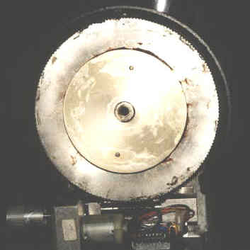
Position the telescope with its tube down or on its side. Remove the Dec clutch knob and washer and use a small Allen wrench to remove the 3 screws holding the Dec drive cover. You may also want to remove the Dec drive assembly which is held by 2 Allen machine screws and the wiring harness which is plugged into a socket on the inside of the fork arm with a modular plug. Then remove the Dec worm gear by wiggling it off the inside clutch plate. The gear should be marked so that, when reassembling the drive, the gear can be replaced in the same orientation as it was originally. See Fig. 1
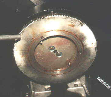
IMPORTANT! You will now need to remove the inner
clutch plate. Use a torch to heat the 2 flat head stainless steel
Allen machine screws for about 5 to 10 seconds. This is important
as the screws are secured with primed Loctite that requires fairly high
torque for removal. Without the heat to break the bond, you may damage
the Allen head of the screw. See Fig. 2.
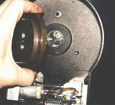
Remove the inner clutch plate from the shaft. See Fig. 3.
| Fig. 1 Worm Gear and Drive | Fig. 2 Removing the Worm Gear | Fig. 3 Removing the Rear Clutch Plate |
 |
 |
 |
REMOVING THE DECLINATION SETTING CIRCLE
The declination setting circle on the left fork arm was probably secured with medium strength Loctite. Wrap the smooth setting circle knob with electrical tape and use a Channel Lock pliers, pipe wrench or strap wrench to loosen it for hand removal. Once removed, you can see the nylon bearing and shaft. The bearing shaft can be measured at this time to verify that it is 1" diameter.
MARKING THE FORK ARMS AND REMOVING ONE FORK ARM
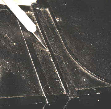
Use an exacto knife with a standard #11 blade to score the fork arm
position on the RA drive. This will help to establish proper fork
arm alignment at the reassembly stage. See Fig. 4. There
is no need to remove both fork arms as removal of one will allow the removal
of the optical tube and aid in securing initial or original fork alignment.
Remove 4 Allen machine screws located under the left fork as shown in Fig.
5. Leave the right fork where the Dec drive is located attached.
When this is done the left fork arm will slip off of the optical tube and
the entire optical tube can be removed from the right fork arm. This
step should be done with care since the entire forkarm/optical tube assembly
comes apart at one time.
| Fig. 4 Marking the Fork Position | Fig. 5 The 4 Fork Bolts | Fig. 6 Nylon Bushing Exposed | Fig. 7 Installing Thrust Washers |
 |
 |
 |
 |
REMOVING THE NYLON BEARINGS AND ADDING A THRUST WASHER
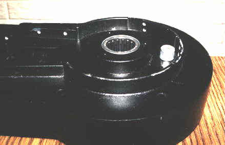
The Nylon bearings are now exposed and can be pushed out by hand. See. Fig. 6. This is a good time to re-grease the factory thrust bearing located on the optical tube and add one additional 0.030" thrust washer to each of the shafts extending from the optical tube assembly. When done, each shaft will have the factory thrust washer, factory thrust bearing, a second factory thrust washer and one additional user supplied thrust washer. The nylon bearing which was removed had a 0.040" thrust dimension. This is replaced with a 0.030" thrust washer to maintain thrust bearing preload. If upon reassembly you find inadequate preload, use a thicker thrust washer should be used. See Fig. 7.
PREPARING THE FORK ARMS FOR BORING AND INSTALLING BEARINGS
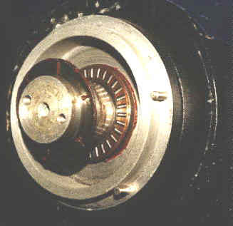
Now is the time to take both fork arms and the RA drive to the machine shop for boring. Pad the base a little and cover with a plastic bag securely taped to prevent aluminum filings from entering the ports, etc. Take the bearings with you for sizing. If you prefer have the machine shop press them FLUSH to the INSIDE of the fork arm. I preferred to do this myself, using a cylinder hone to approach the final OD dimension. Then, I used primer and Loctite to allow potential removal with heat and hand tools if that should ever be necessary. Finally I used a thick washer and a hammer to gently seat the bearing. See Fig. 8.
For additional information on boring the bearing holes
use this link.
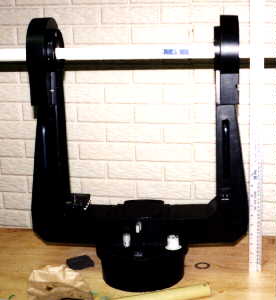
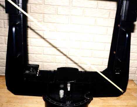
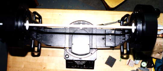
| Fig. 8 Inserting the Needle Bearing | Fig. 9 Leveling the Fork Arms | Fig. 10 Squaring the Fork Arms | Fig. 11 Lining Up Fork and Base |
 |
 |
 |
 |
CHECKING AND ADJUSTING THE MOUNT TO BE ORTHOGONAL
Before reassembly, we MUST verify that the fork will be orthogonal upon assembly. Failure to do this will result in poor pointing accuracy and unexplained field rotation during long exposures because the mount will not properly polar align. Drift alignment will not cure this for full sky but only for the local area where alignment is executed. This step, well done, will improve pointing accuracy of the mount.
The marks made on the fork prior to disassembly are used as the starting point during reassembly. If everything was aligned at the factory during manufacture and has not drifted for some reason, reassembly to these marks will be very close to correct. This must be verified now. Tighten the 4 fork arm bolts. Place the RA/fork assembly on a flat table as shown in Fig. 9. It is important for the table to be flat and with room for the entire telescope assembly to move freely about the RA axis. The assembly must also be firmly in contact with the table surface. Insert a length of steel rod or rule known to be perfectly straight through the forks and measure the distance to the flat table surface from both forks. Do this with the forks rotated 180 degrees. The measurements should all be equal if the arms are the same height and the table and base of the RA mechanism are in good contact. Comparing these measurements will tell you if one of the arms is taller than the other. If so shim the shorter arm as necessary to get the fork heights equal. Repeat this procedure to check for equal fork dimensions. Measure the diagonal dimensions of the fork as shown in Fig. 10 and shim as necessary to get equal measurements. This insures the fork arms are square. Finally, looking from above, see that the fork arms are parallel to the bottom of the fork edges. See Fig. 11. At this point, the RA drive and fork arms should be well aligned and square with each other.
Now mark the correct position of the fork arms, as adjusted with the above procedure. Remove the left fork arm in preparation for reassembly of the optical tube and bearings.
INSTALLING THE OPTICAL TUBE AND THE DEC CLUTCH
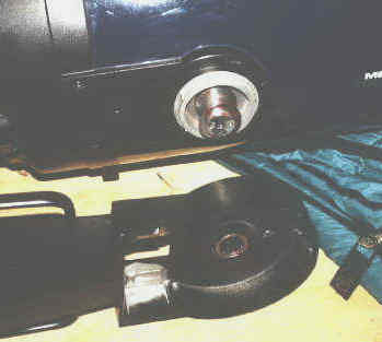
Position the optical tube on its side and insert the 1" shaft along with the thrust bearing assembly into the bearing on the Dec drive fork. Before assembly, DON'T forget to pack the new needle bearings and thrust bearings with grease by forcing it into the bearings with your fingers. See Fig. 12. Finally install the left fork to the marks you have made. Insert and tighten the 4 fork bolts. Note the amount of preload that is applied to the thrust bearings. If not enough, add a thicker thrust washer to each side to remove any lateral play from the bearing assembly.
Install the Dec clutch and worm gear in reverse order of disassembly.
Do not fail to use Loctite and primer. The Loctite fills gaps and
assures the Dec clutch assembly doesn't work loose. Finally add the
Dec clutch washer and knob. CAUTION! Set the scope upright
and check the new bearings with caution. With the Dec clutch unlocked
friction is very, very low and the optical tube may move surprisingly easily.
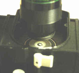
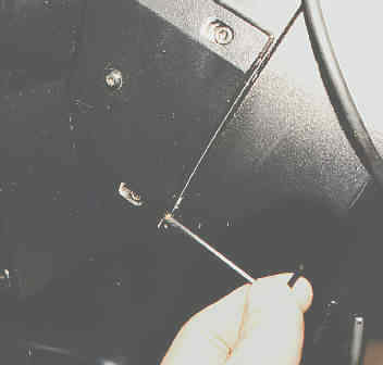
| Fig. 12 Reassembly Step | Fig. 13 Light Cone and RA Bearing Screw | Fig. 14 Adjusting the Tube Mount Plate |
 |
 |
 |
FINAL OPTICAL TUBE ADJUSTMENTS AND ALIGNMENT
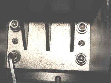
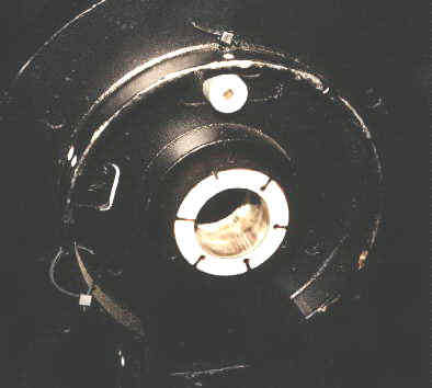
Position the telescope under a diffuse light source such as a fluorescent fixture and point the tube straight up. Remove 2 Allen head screws holding the RA bearing cover and remove it. Insert a long focal length eyepiece into the visual back holder. Adjust the focus knob for a light cone that is just large than the RA bearing retaining screw. See Fig. 13. If the optical tube is not aligned to the Dec axis, the light cone will be offset to the left or right. Next, LUBRICATE the thread on two 4/40 1" Allen head machine screws and thread into the ends of the optical tube shaft mounting plates. If these screws don't thread in smoothly, chase the threads with a 4/40 tap, otherwise there is a good possibility the screws will seize and break. Next, slightly loosen the 3 optical tube shaft mounting plate bolts on the side where adjustment is needed. For example, if the light cone is offset to the right, you will loosen and adjust the left side. See Fig. 14.
When the light cone is centered, tighten the 3 mounting plate screws. Now is a good time to install and precisely set the declination setting circle with respect to the optical tube. With the light cone centered over the RA bearing retaining screw, apply primer, then Loctite to both sides of the setting circle spacer and threads. Thread onto the shaft and position the setting circle for exactly 90 degrees. Reinstall the RA bearing cover.
INSTALLING AND ADJUSTING THE DEC DRIVE ASSEMBLY
With the huge reduction in friction within the Dec drive as a whole, the worm float may not need to be reduced below the factory settings as the current spring tension may very well be adequate to maintain worm contact with the worm gear. No retrograde motion was observed and excellent worm to worm gear contact was maintained during motor reversal. Initial backlash setting of 20 seems to be more than enough on a well balanced telescope. If the worm drive platform moves radially with respect to the worm gear, see a discussion about setting the lash for the Dec drive elsewhere on this web site.
FINAL CHECKOUT
Balance the telescope and release the RA lock and the Dec clutch.
Remember that even a slightly unbalanced optical tube will initiate rapid
motion of the tube about the Dec axis. So hold on to the tube until
you get the feel of the low friction action. Start by moving the
telescope by hand across the full range of declination and compare the
smoothness to that of the RA axis. Attach the Dec cable and power
up the telescope. Watch the worm gear platform carefully and check
that the worm gear maintains intimate contact with the worm gear after
reversal action. If all is well at this point, you have now completed
your Dec drive system modification which has dramatically reduced friction
and improved performance. The orthognality of the mount has also
been checked and adjusted and the optical tube has been aligned with the
RA axis. These adjustments will insure maximum pointing accuracy.
As a bonus, the declination setting circle has been adjusted to the optical
axis. All this in less than 1 1/2 hours. (Michael's time not Doc
G's.)
Addendum by Doc G: I am very excited by the excellent detail Michael has given for this rather complex modification of the LX200 Dec bearings. Even if one does not do the modification, the description of the techniques for adjusting the fork mount are of considerable value. I have thought about this sort of modification ever since my first Dec drive went out. I am most pleased to have the chance to publish Michael's work here. I imagine we will, over time, make some adjustments to the text and images. Your suggestions and comments are welcome.
APPENDIX 16 March 1998 Return to Beginning
A major problem with removing the clutch plate screws has been experienced by several persons. The techniques described below should help significantly. Use an allen wrench that is in good condition with a handle so that appreciable force can be applied against the screw when trying to remove it. Heat the screw directly with hot part of the torch flame so as to soften the Loctite. It might take 20 seconds or so. If the screw is overheated, it might be wise to let it cool slightly while applying torque to remove it. The screw will shrink slightly but the Loctite will stay soft. If the screws are damaged replace them with new ones. You might want to use torx screws as replacements.
The bore in the fork arm should be 0.001" to 0.003" oversized. The bearing will be easily held in place with Loctite since this is a slow speed application. (I hand honed mine to a smooth fit that went together with finger pressure - Doc G) If you under bore, you may need to cool the bearing to get it in. The fit does not have to be that tight.
There has been some variation in shaft size found. If the shaft is 1.00" down to 0.994" it should fit fine in the bearings recommended. If the shaft is too much undersized that is a problem that can be solved by using the next size smaller bearing which is 0.984". This complicates the job since the shafts need to be turned down. It is better to avoid this problem by accepting a bit of extra clearance. Fir this application tight tolerances are not necessary since the bearings are very heavily loaded in one direction.
It is important to have adequate lateral preload on the thrust bearings. The removal of the nylon washers takes out about 0.80" total. Thus must be replaced with thrust washers. The forks when assembled should grip the tube very firmly. (No play at all with several pounds of pull applied.)
It has been pointed out that in some cases the washers under the bolts holding the forks might have become cupped. Inspect them and if they are damaged, replace them with slightly thicker washers. This will allow fine adjustment of the fork positions.
With no clutch plates installed the tube will oscillate several (up to 12) cycles, showing almost no friction. With the clutch and worm gear in place the friction of the clutch will of course reduce the freedom of this swing. As it should, since it is locked up in operation.
After modification the bearing friction has been almost completely removed. The declination drive mechanism should now be readjusted for optimal performance. This is done by adjusting the drive platform position to tight tolerance as described in some detail on this web site. See: LX200 Mechanical Fixes/Repair of Declination Drive.
APPENDIX 21 March 1998 Return to Beginning
This appendix includes a few more comments from Doc Gs experience with rebuilding the declination drive on his 10" LX200 and a few comments received from others who have successfully done the rebuild.
It has become clear that several persons who have done this modification have excellent skills in the machine shop. Those who try this should judge carefully which techniques are best for them to apply. Special thanks to Jim Mettler, who worked on Don Dillinger's telescope and Bobby Middleton for their feedback. Don writes, "I would not even consider the "Hart forkotomy and declinoplasty" were it not for the significant ongoing and refractory performance variations that I found unacceptable -- not to mention the fact that I could talk Mr. Mettler into doing the surgery for me!" Well put (Doc G). As another bard would say "If 'tis done when 'tis done, then better 'tis done quickly."
A good substitute bearing is the SCE1616PP INA. It is slightly smaller with sealed ends. Your scope may have "pre-damaged" clutch plate screws. If so you can slot the screw with a Dremel cut off wheel and remove, after heating, with a slotted screwdriver. Both fork arms can just as well be removed without marking. Reassembly and realignment is quite easy using standard machine shop tools and techniques. The bearings can be pressed into the bored mount using a mill to insure getting them started squarely.
An accurate, sensitive level (0.005" per foot) and a piece of precision shafting can be used to do the fork arm alignment. The procedure is somewhat involved, so will not be described in detail here. Basically the telescope RA base should be leveled. This can be done on a tripod. Then the shaft can be leveled with respect to the RA base by raising one of the fork arms with respect to the other until the shaft is level. (I also used this technique, Doc G) One arm is placed and the other arm shimmed up to get alignment and tightened. Remove the arm that did not need shimming, it is as low as possible toward the base and will be restored to the same location when the OTA is put into place and the arm reinstalled.
Re-install the dec clutch, gear and motor drive. Using the level, place it across the corrector plate end of the OTA and level. Set the dec setting circle to 90 degrees and tighten. Using a good level makes the above operations accurate and objective. The perpendicularity of the dec axis with respect to the RA axis is the important parameter in this adjustment.
Upon first light, the results were good. After standard Meade polar alignment was completed, pointing accuracy was within 3 to 4 arc minutes over the whole sky. Drift, without precision drift alignment, was 10 arc minutes in 2 hours. This is a fine result, thanks Don and Jim for your comments.
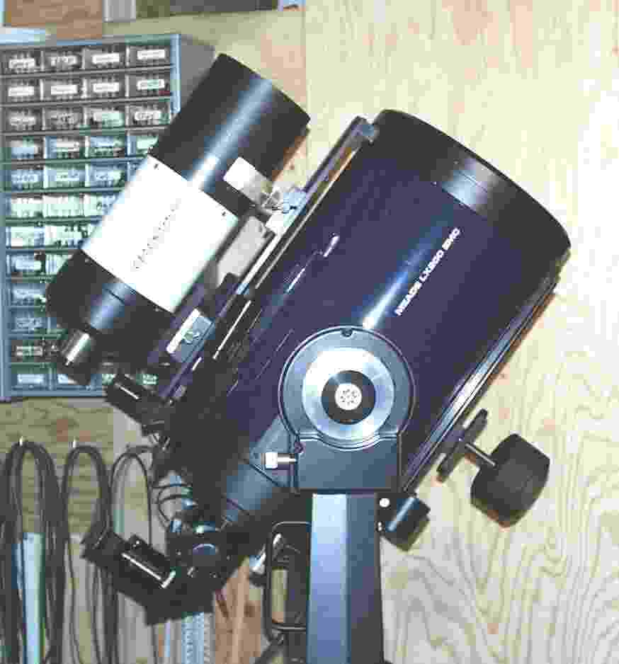
I (Doc G) have worked with the newly modified 10" in the basement laboratory
and tested it for balancing capability and load carrying capacity.
The scope is shown in the following photograph with a considerable load
of equipment. The C-5 is quite heavy and is carried in a sturdy mounting
yoke. Notice that the tube is coarsely balanced with two 2 pound
Meade weights and fine balanced with the Losmandy 2D balancing bar.
A 5 and 2 1/2 pound weight are on the Losmandy bar. With this heavy
but balanced instrument, only a few ounces of weight moves the scope easily
and it stays where pushed in all directions. The motors run the scope
without strain. All in all a very satisfactory unit mechanically.
For information about the C-5 mount see: Guider
Scope Mounts
 |