 |
 |
Discussion of Declination Drive Design
The event that brought on this article is posted at the end. (For dec run away experience press here.)
The declination drive for the LX 200 is discussed in some detail herewith. Since the RA drive is essentially identical, the commentary here should also serve to describe its basic operation.
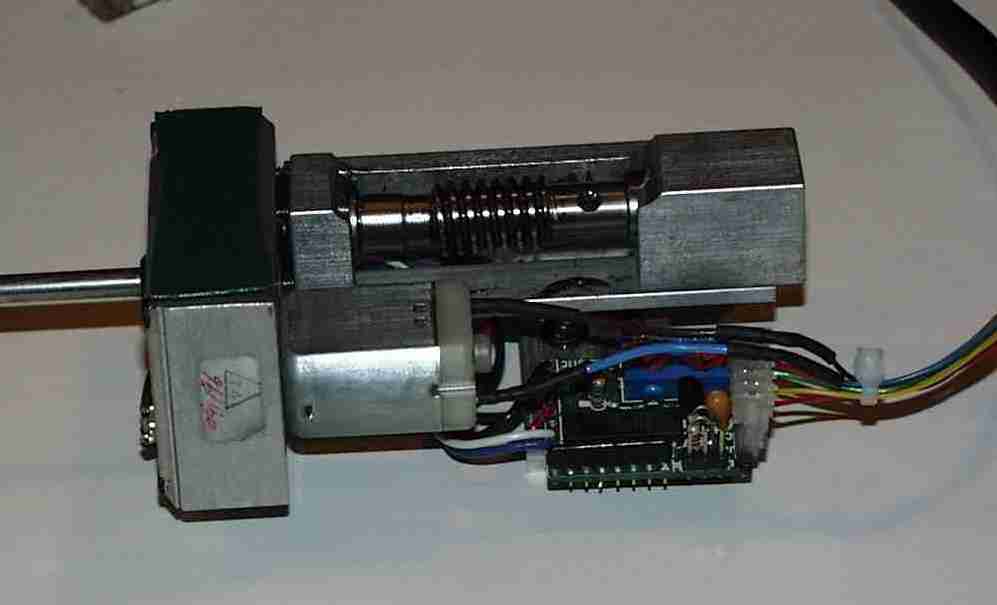
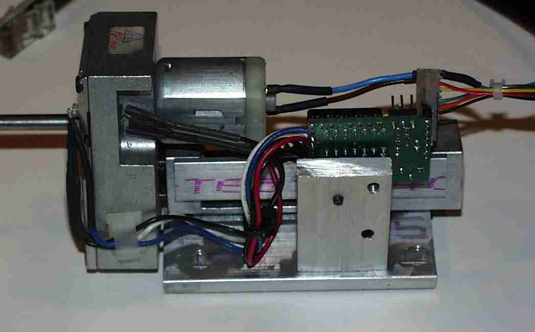
The drive is shown on the left from the front top view as it is delivered from Meade. This particular drive is a spare that I purchased from Meade for $150.00. It is held in my personal stock of parts to replace a drive that might go out of service for some reason on one of the two LX200 telescopes that I am responsible for keeping in good repair. On the right, the drive is shown from the bottom. The mechanical operation of this unit has been discussed at length elsewhere in these pages. Our concern in this discussion is with the electrical and electronic parts of the drive.
The tiny motor that drives the telescope through a gear train and worm is shown clearly. The motor shaft rotation is reduced by the gear train in the housing on the left by 60 times where it is coupled to the worm. The worm in turn drives the worm wheel (the large spur gear in the declination drive, not shown) which has 180 teeth. The worm turns only when a declination correction is required. The RA drive is identical except that the hole seen in the worm shaft in the photograph on the left has a magnet in it which operates a switch that establishes the starting point for PEC training. It, of course, turns continually at one (1) turn every eight (8) minutes to move the RA position at sidereal rate.
The small circuit board has a dual Schmitt trigger circuit chip which
converts the signals from two photo detectors to a bi-phase signal that
is sent to the computer board. The photocells detect light from a
pair of small lights through the encoder mask and encoder wheel encased
in the gear box housing.
 |
 |
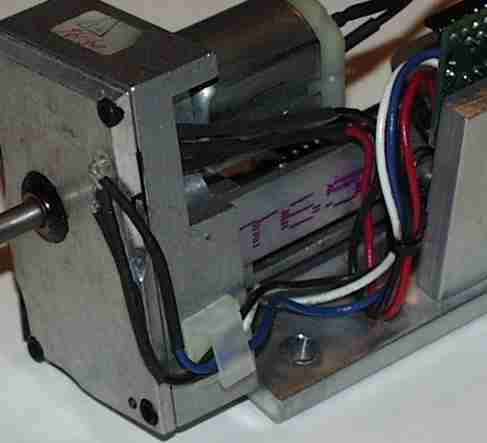
Close-up of the photocells and light arrangement are shown in the following two photographs. On the left are shown the two photo detectors which are stuck into holes in the gear box housing and cemented in place. The leads on the photocells are bent very sharply and connected to rather heavy wires, then clamped in a plastic clamp stuck to the housing. This is a possible trouble spot. The leads coming out of the photocells are very brittle and are bent too sharply, in my opinion. They are cracked slightly at the bend in this example. The leads going from the photocells to the circuit board are rather stiff and unfortunately the plastic clamp is not positioned correctly nor is it closed tightly enough to hold the wires and thus relieve the stress on the photocell leads as intended. This area should be inspected carefully if there is a declination drive runaway problem.
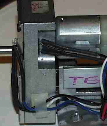
The photograph on the right shows the photocells, on the outside, and the lights on the inside of the housing. The encoder mask and encoder wheel lie between the two. When the light path is interrupted, the encoder sends signals via the Schmitt triggers to the computer where they are counted to establish differential position information for the computer. The wires to the lamps are also quite heavy and put excessive stress on the tiny light leads in my opinion.
The circuit board contains, in addition to the integrated circuit chip,
two potentiometers which are used to adjust the level at which the trigger
circuits operate. These can only be adjusted with use of an oscilloscope
which is used to observe the signal while the motor is turning the encoder
wheel. A set of test terminals is provided for this adjustment.
 |
 |
In one case of declination drive runaway, the cause was breaking of one of the leads to one of the photocells. I tend to believe that many declination drive runaways, that are not do to bad connections, are due to failures in the declination drive circuits in this assembly. Unfortunately, since the declination drive motor, encoder and all the rest of the system including the computer are part of a closed loop control system, it is difficult to find the problem without appropriate test jigs and procedures.
Date: Sat, 13 Jun 1998 20:13:32 -0500
From: "R. A. Greiner" <ragreiner@mailbag.com>
To: mapug@shore.net
Well, this should give all you mapuggers who have had runaway dec drives a chuckle. It has just happened to me. (alleged dec expert??) This morning I went to the Madison Astronomical Society site for our annual picnic. I got there two hours early to clean up the observatory and get the LX200 polished and running for Solar observation. When I turned on the scope. blewwy!! running dec with no control whatever. Dec plugs check all three of them! Nothing Turn it on and turn it off a few times. Nothing!! Talk to it. Nothing!! Talk in no uncertain terms. Nothing!! Kick the pier. Nothing!! Kick the pier harder. Nothing!! (bent toe!)
Took off the dec drive cover and wiggled everything carefully. Nothing!! Wiggled everything harder. Ah Ha a momentary stutter. Turn off the scope. Check every wire visually very carefully. Ahh Haa!! broken wire on one of the encoder photocells. The wire was broken right at the cell. (in fact the lead was broken right at the seal) Very difficult to re-solder. But did re-solder using tweezers and hot soldering gun. Turned on scope. All fixed!! This fix required lots of luck and a tiny bit of talent. :-)
Thus another way to have and find a dec drive runaway. The picnickers enjoyed viewing the Sun just fine. Scope continued to work perfectly all day. They never knew the trouble I've seen. :-) More LX200s sold on the spot. :-)
The scope tracked the Sun with minor centering corrections for hours, even without changing the frequency of the drive. Great spots with nice detail using the Thousand Oaks filter. When it works, boy it really works.
Doc G <http://www.mailbag.com/users/ragreiner>